
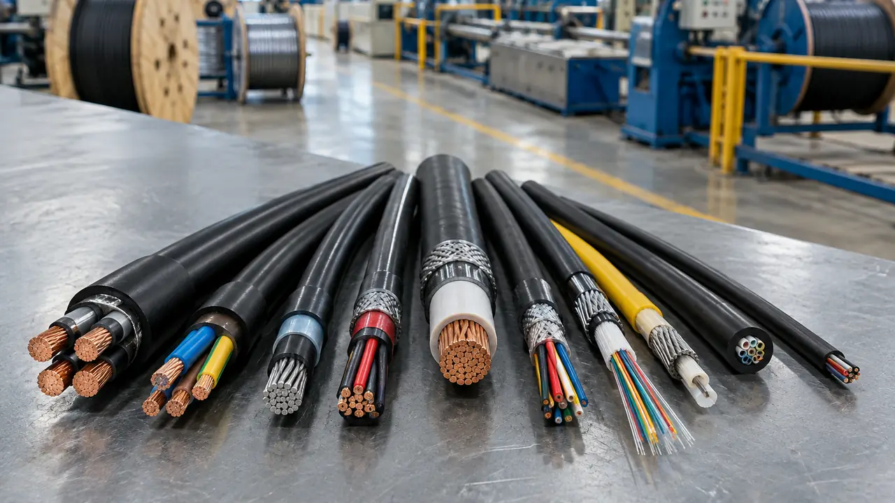
Why buyers should think in layers
A datasheet lists a cable as a stack: conductor, insulation, assembly, perhaps a screen or armour, and an outer sheath. A factory prices it the same way, layer by layer, because each layer is a separate material and often a separate pass through a separate machine. When a quote looks cheap, the saving is almost always hidden in one layer: a conductor with fewer or thinner wires, an insulation wall at the low end of tolerance, fillers replaced with less material, or a sheath that is thinner than the standard asks for.
IEC 60502-1, the common reference for 0.6/1 kV power cables, describes the possible layers in order: conductor, insulation, fillers and inner covering, metallic layers such as screen or armour, and the oversheath. Not every design has every layer. A building wire has two; a medium-voltage armoured cable can have nine or ten. The sections below walk through them from the centre outwards.
Conductor and insulation
The conductor carries the current and is usually the largest cost item, because copper and aluminium make up roughly 80% of the cost of a typical cable according to listed manufacturers' disclosures. It is specified by material, cross-section and class under IEC 60228: Class 1 solid, Class 2 stranded, Class 5 flexible and Class 6 extra flexible. The test that matters is the maximum DC resistance at 20 C; for a 25 mm2 copper Class 2 conductor it is 0.727 ohm/km. A conductor that passes this value carries enough metal, whatever its diameter looks like. More on materials is on our conductor materials page.
The insulation is the extruded layer that holds the voltage. PVC is rated for a 70 C conductor temperature; XLPE is rated for 90 C continuous and 250 C in a short circuit, which is why most 0.6/1 kV power cables now use XLPE. On the reference 0.6/1 kV Cu/XLPE/PVC 4x25 mm2 cable from a partner plant catalogue, the XLPE wall is 0.9 mm. Thickness is measured on samples from the drum and compared with the nominal and minimum values in the standard.
Medium-voltage cables add two thin semiconductive screens, one under and one over the insulation, to keep the electric field smooth. On the reference 8.7/15 kV 3x95 mm2 cable, the XLPE wall between them is 4.5 mm, five times the low-voltage figure. The insulation and sheaths page compares the compounds.
Core identification, fillers and binder
Each insulated core is identified, usually by colour for power cables and by printed numbers for multicore control cables. The identification has to match the market: brown, black, grey, blue and green-yellow under the IEC convention, other schemes elsewhere, as covered in our post on cable core colour codes.
When several cores are laid up together, the gaps between them are packed with fillers so the cable is round, and the bundle is held with a binder tape. On the reference LV cable these are PP filler and non-woven tape. Fillers look like a minor detail, but they set the roundness of the cable, which affects how well glands seal and how the cable sits on a drum.
Inner sheath, screens and armour
Armoured cables need a bed for the armour. The inner sheath or bedding is an extruded layer over the laid-up cores; on the reference 0.6/1 kV Cu/XLPE/STA/PVC 4x35 mm2 cable it is 1.2 mm of PVC. Over it sits the armour: steel tape (STA, 0.2 mm on the reference model), steel wire (SWA) for multicore cables, or aluminium wire (AWA) for single-core AC cables, where steel would heat up from eddy currents. Our armoured cables page shows the full construction.
Medium-voltage cables carry a metallic screen instead of, or in addition to, armour. On the reference MV cable it is a copper tape screen over each core, which carries charging and fault currents and gives the cable a defined earth potential. Screens and armour are explained side by side on the armour and screens page.
Outer sheath and marking
The outer sheath protects everything inside from water, abrasion, sunlight and handling. PVC is the common choice; LSZH compounds are used where smoke and halogen gas matter, tested to IEC 61034 and IEC 60754; PE is used where water resistance or burial matters more than fire behaviour. On the reference LV cable the PVC sheath is 1.8 mm; on the MV reference it is 2.8 mm. The sheath also carries the printed legend and metre marks, which is the subject of our post on sheath printing.
| Layer | 0.6/1 kV 4x25 mm2 XLPE | 0.6/1 kV 4x35 mm2 STA | 8.7/15 kV 3x95 mm2 |
|---|---|---|---|
| Conductor | Stranded annealed copper | Stranded annealed copper | Compacted copper |
| Semiconductive screens | None | None | Conductor and insulation screens |
| Insulation | XLPE 0.9 mm | XLPE 0.9 mm | XLPE 4.5 mm |
| Fillers and tape | PP filler, non-woven tape | Fillers, tape | Fillers, tape |
| Inner sheath | None | PVC 1.2 mm | None |
| Metallic layer | None | Steel tape 0.2 mm | Copper tape screen |
| Outer sheath | PVC 1.8 mm | PVC 1.8 mm | PVC 2.8 mm |
| Overall diameter | approx. 25 mm | approx. 30 mm | approx. 61 mm |
| Weight | approx. 1,292 kg/km | approx. 2,067 kg/km | approx. 5,403 kg/km |
The table shows how quickly weight climbs as layers are added: armour and an inner sheath take a 4-core cable from about 1.3 to about 2.1 tonnes per kilometre, even though the conductor grows only one size. That weight sets drum size, freight and handling.
Using layers to compare quotes
When two offers for the same description are far apart, compare them layer by layer before comparing price per metre:
- Conductor: ask for the class and the DC resistance record per drum, not just the nominal size.
- Insulation: compare compound and nominal thickness; a cheaper offer sometimes quotes PVC where you asked for XLPE.
- Assembly: check core count, fillers and whether an inner sheath is included under armour.
- Metallic layers: confirm armour type and size, or screen type and cross-section on MV cables.
- Sheath: compare material, nominal thickness and overall diameter; a diameter well under the datasheet is a warning sign.
The desk writes this table into every spec sheet and checks it against the routine test records before shipment. To start one, send the designation and quantities through the quote form, or read how cable designations are decoded first.