
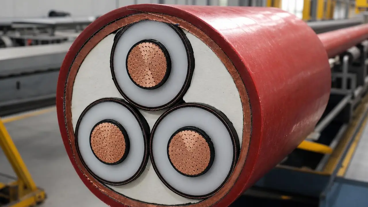
What this cable is
Medium voltage cable carries power between substations, ring main units, transformers and large motors, and collects power from inverter stations on solar farms. The reference construction on this page is the 8.7/15 kV three-core 95 mm2 Cu/XLPE/CTS/PVC cable from a partner plant catalogue. Each core is a compacted annealed copper conductor, wrapped by an extruded conductor screen, 4.5 mm of XLPE insulation, an extruded insulation screen and a copper tape screen. The three cores are laid up with fillers and a binder tape and covered by a 2.8 mm PVC sheath. The cable is about 61 mm overall and weighs about 5,403 kg per kilometre, and the conductor resistance limit is 0.193 ohm/km at 20 C, the IEC 60228 Class 2 figure for 95 mm2 copper.
The rating 8.7/15 kV means 8.7 kV between conductor and screen (U0) and 15 kV between phases (U). The U0 value matters: on networks where an earth fault can persist, engineers often choose a higher U0 class for the same system voltage. That decision belongs to your project engineer and network operator.
Why the screens matter
Above 1 kV the electric field inside the insulation must be smooth and contained. The conductor screen fills the gaps between strands so the field does not concentrate at sharp points; the insulation screen gives a clean outer boundary; the copper tape screen carries charging current and earth fault current and holds the outside of the cable at earth potential. A void or a rough interface between these layers is where partial discharge starts and slowly erodes the insulation. That is why plants extrude the three layers together in one pass, and why every MV drum should come with a partial discharge record per IEC 60885-3, typically 10 pC or less at 1.73 U0. The semiconductive layers article explains the physics in plain terms.
Voltage classes and sizes
IEC 60502-2 covers rated voltages from 3.6/6 kV to 18/30 kV. The partner plant catalogue behind the reference stops at 8.7/15 kV; 12/20 and 18/30 kV cables are matched to other plants with the right extrusion line and test equipment, case by case.
| Rated voltage U0/U | Typical network | Sizes | Sourcing note |
|---|---|---|---|
| 3.6/6 kV | 6 kV plant and motor feeds | Single core 25-630 mm2, three core 25-400 mm2 | In partner catalogue range |
| 6/10 kV | 10 kV distribution | As above | In partner catalogue range |
| 8.7/15 kV | 10-15 kV distribution, solar collectors | As above; reference 3x95 mm2 | Reference model on this page |
| 12/20 kV | 20 kV distribution | Per plant datasheet | Matched to other plants per project |
| 18/30 kV | 30-33 kV networks, wind and solar | Per plant datasheet | Matched to other plants per project |
Single-core cables in trefoil suit large currents and long pulls; three-core cables are easier to lay and joint on distribution routes. Size selection depends on the installation method, fault level and screen earthing, set by your engineer under IEC 60364-5-52 or the network operator's rules. We do not publish current ratings. For the LV side of the same project, see LV XLPE power cable.
What you can change
Conductor, screens and insulation thickness are set by the standard for the voltage class and should not move. Options that change routinely are the metallic screen (copper tape or copper wire, sized to the earth fault current your engineer specifies), the sheath material (PVC, PE for wet burial, or LSZH for buildings and tunnels), water blocking tapes, and armour for direct burial; see armour and screens. Sheath print with your brand, construction, voltage, year and metre marks is fixed on the spec sheet.
Tests, drums and lead time
Routine tests on each MV drum include conductor resistance, the voltage test at 3.5 U0 for 5 minutes under IEC 60502-2, and partial discharge. Checks such as insulation thickness, outer diameter and thermal ageing are run on samples from the production lot. For MV the desk usually looks first at plants in Yixing and in Ningjin, whose cluster was listed by the industry ministry in 2024 for low and medium voltage and new energy cable, and checks each plant's own test bay rather than relying on the cluster name. The desk collects these records per drum before loading and can arrange witness testing; see testing and inspection. MV cable is heavy, so drum size is set by weight and the minimum bending radius, and drum lengths are agreed against your joint positions. Lead time is longer than for LV because of screen extrusion and testing, and depends on copper booking and the production slot; it is confirmed in writing for each order. See MOQ and lead time and send your BOQ through the quote form.