
What an ADSS cable is
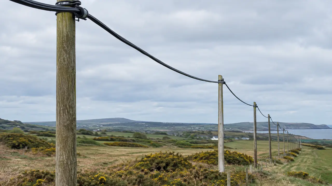
ADSS stands for all-dielectric self-supporting. The cable hangs between poles or towers on its own strength, with no messenger wire and no metal anywhere in the construction, so it needs no earthing and can run along power line routes and through lightning-prone areas. The reference construction on this page is a 24-core, single-sheath ADSS cable of the 100 m span class, taken from public datasheets: a central FRP (glass-fibre reinforced plastic) rod, loose tubes holding fibres in gel stranded around it, a layer of aramid yarn that carries the tension, and a PE outer sheath. Overall diameter is about 10 mm and weight about 80-110 kg per kilometre depending on the maker, and the maximum allowable tension (MAT) quoted for this class runs from about 1,700 to 2,700 N across datasheets.
Those spreads are normal. Two plants can both call a cable "24-core, 100 m span" and still differ in aramid yarn count, sheath thickness and design assumptions. That is why the desk compares datasheets line by line before anyone compares price per metre, and why the figures here are reference values rather than a specification.
Span is a loading calculation, not a label
A span class means something only together with the conditions it was calculated for: sag, wind speed, ice thickness and temperature. One public datasheet for this class states its design at 1.5% sag, 25 m/s wind and no ice. Another maker's data for a similar 24-core cable allows about 100 m in light and medium loading zones but only about 50 m in a heavy-ice zone. The same cable can halve its span when the weather assumptions change.
| Input | Why it matters | Usually supplied by |
|---|---|---|
| Span lengths and allowed sag | Sets the tension the aramid layer must carry | Line designer |
| Wind speed and ice thickness | Adds load; heavy ice can cut the usable span sharply | Local loading zone or utility rules |
| Temperature range | Changes sag and sheath behaviour | Site data |
| Line voltage and attachment point | Decides PE or AT sheath | Utility or line designer |
| Clamp and damper type | Hardware is matched to OD and MAT | Installer, confirmed by the plant |
The aramid yarn count is what the plant adjusts for these inputs, so a quote without stated loading conditions cannot be compared with one that has them. The ADSS span selection article walks through each input.
PE or AT sheath
On a route shared with power conductors, the electric field at the attachment point can cause dry-band arcing and tracking on a standard PE sheath. Anti-tracking (AT) sheath compounds are used where the field is high enough to need them. Published thresholds for when AT becomes necessary disagree with one another, so the desk does not apply a fixed voltage rule: the choice follows a field strength calculation for your line voltage and attachment position, made by the line designer or the plant's engineering team and confirmed in writing. An AT sheath adds some weight; one maker's 48-core data shows roughly 8-9 kg/km more than the PE version.
Longer spans or heavier loading may call for a double-sheath design, with an inner MDPE sheath, the aramid layer between the sheaths, and an outer PE or AT sheath. The plant's span table for your conditions shows which design is needed.
Standards, and where ADSS sits
ADSS cable is commonly specified to IEEE 1222-2019 and IEC 60794-4-20, with fibres to ITU-T G.652.D on most single-mode routes. Cabled single-mode fibre is compared with the cabled fibre limits in the G.652 tables, 0.4 dB/km at 1310 nm and 0.3 dB/km at 1550 nm; product values are per datasheet and per drum record. OPGW, which replaces the overhead earth wire and contains metal, is a different product under IEEE 1138-2021; see OPGW vs ADSS. For duct and buried routes, see outdoor fibre cables.
Hardware, drums and installation limits
Tension and suspension clamps and vibration dampers are chosen to the cable's diameter and MAT, so the diameter on the datasheet must match the cable on the drum; a difference of 0.5 mm can affect clamp fit. The desk fixes OD and tolerance on the spec sheet and measures it at inspection. One reference datasheet gives a minimum bending radius of 25 times the diameter during installation and 12.5 times in service, with an operating range of -40 to +70 C; your installer works to the datasheet of the cable actually supplied.
ADSS ships on wooden or steel-wood drums, with 2 km and 4 km lengths common and other lengths by order. Both ends are capped, and the drum plan records drum number, length and fibre count. Attenuation records and OTDR traces per fibre travel with each drum; see fibre OTDR test reports. Lead time depends on fibre and tube scheduling and is confirmed in writing for each order; see MOQ and lead time.
How the desk runs an ADSS order
- You send fibre count and type, span lengths, loading conditions, line voltage if the route is shared, total length and port through the quote form.
- The desk shortlists partner plants in the Wuhan and Qidu fibre clusters that make ADSS to IEEE 1222 or IEC 60794-4-20 and asks for their design for your conditions.
- The spec sheet fixes fibre type, aramid design, sheath type, OD, MAT and drum lengths, plus the hardware list if you need it.
- Drum records are checked against the spec, and drums are inspected for length, end caps and print before loading.